ProcessPublished 6 min read
How to Prepare CAD Files for 3D Product Animation
To prepare CAD files for 3D product animation, export neutral formats like STEP or IGES, clean up unnecessary features, set appropriate tessellation, name parts clearly, suppress hidden internals, and send the cleaned assembly with material references.

Key takeaways
- Use neutral CAD formats such as STEP, IGES, Parasolid, FBX or OBJ for reliable exchange.
- Remove hidden fasteners, construction geometry and unnecessary details to keep the model light.
- Set tessellation chord height and angle to balance visual smoothness and file size.
- Give each part a clear, descriptive name and organize the assembly with logical groupings.
- Suppress internals that are not needed for the animation, but keep them if an exploded view or mechanism requires them.
- Send the cleaned CAD file together with material references, texture images and a brief note on the desired animation.
To prepare CAD files for 3D product animation, export a clean neutral format, remove unnecessary features, set proper tessellation, name parts clearly, and suppress hidden internals.
This article walks through each step of the preparation process, from choosing the right file type to organizing the assembly for the animator. It explains common pitfalls and shows how a well‑prepared CAD file saves time and improves the final animation quality.
Which CAD formats work best for animation?
Neutral formats are the safest starting point for most animation pipelines. STEP (ISO 10303) and IGES preserve the exact geometry without tying the file to a particular CAD system, which reduces translation errors. Parasolid (.x_t), FBX and OBJ are also widely accepted and can carry colour or texture information if needed. If you know the animator uses a specific native package, sending a SolidWorks assembly or a Rhino file can work, but be prepared to provide a neutral backup in case of compatibility issues.
Avoid sending only tessellated mesh formats such as STL or 3MF unless the animator explicitly requests a mesh for a specific effect like a rough‑surface simulation. Those formats lose the underlying solid model and make later edits, such as changing a fillet radius or re‑posing a mechanism, much more difficult.
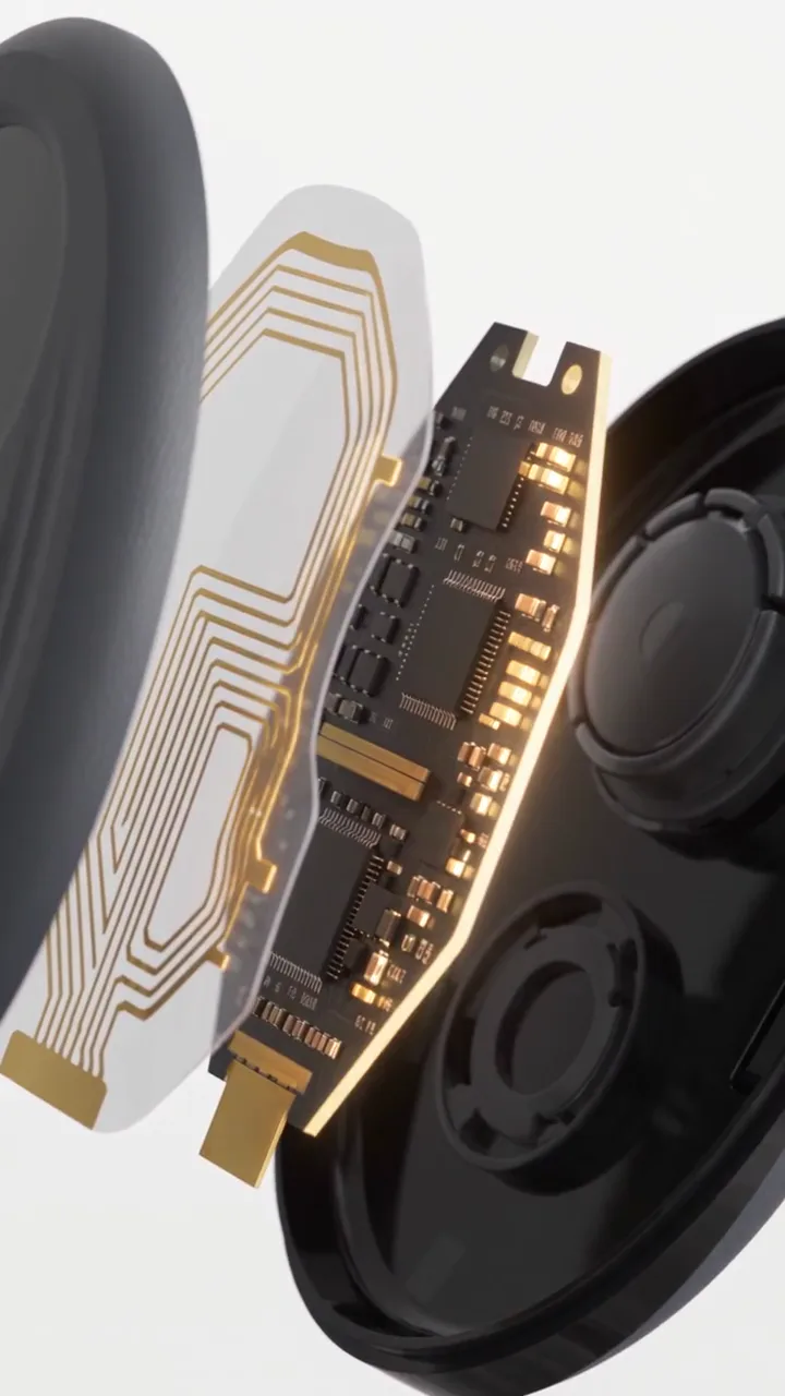
You can see how neutral files are used in practice by looking at the smart sensor exploded view animation, where the original STEP file was cleaned up and tessellated before the housing, flexible circuit and PCB were separated for the exploded sequence.
Cleaning up the model: what to remove and keep
Start by suppressing any internal hardware that will not appear in the final video. Screws, nuts, washers, retaining rings, pins and hidden fasteners can be removed unless they are part of a mechanism you intend to animate, such as a screw‑driven lift or a latch that opens a cover. Next, delete construction geometry: sketches, reference planes, coordinate systems, axes and any design tables that were used only for modelling. These items increase file size and can confuse the animator when they try to isolate parts.
Keep the outer shells, visible covers, displays, buttons and any moving components that will be shown in the animation. If a part has both a visual and a functional role (for example, a gear that also serves as a decorative element), retain it but consider simplifying non‑essential details like tiny fillets or cosmetic textures that do not affect the silhouette.
A useful habit is to create a dedicated “animation” configuration or display state in your CAD file where you suppress all unnecessary features and then export that state. This keeps the original design intact for engineering while giving the animator a clean starting point.
Setting tessellation for visual quality
When you export a neutral format, most CAD systems let you define the tessellation quality. Two main parameters control the mesh: chord height (sometimes called maximum deviation) and angular tolerance. Chord height is the greatest distance allowed between the true curved surface and the flat triangles of the mesh; a smaller value yields a smoother surface but increases triangle count. Angular tolerance limits the angle between adjacent triangles; a smaller value prevents faceting on gently curved surfaces.
For most consumer‑electronics or household products, a chord height of 0.05 mm to 0.1 mm and an angular tolerance of 1° to 3° give a good balance. If the product contains very small details—such as a micro‑textured button or a thin wire—reduce the chord height to 0.02 mm or less. Conversely, for large, simple housings you can raise the chord height to 0.2 mm to keep the file lightweight.
Always preview the mesh before exporting. Look for visible flat spots on cylinders, spheres or curved surfaces; if you see them, lower the chord height or angular tolerance until the surface appears smooth. Remember that the animator can re‑tessellate if needed, but starting with a suitable mesh saves time and avoids surprises during rendering.
Naming parts and organizing the assembly
Clear part names make it much faster for the animator to assign materials, hide or show components, and build exploded views. Use descriptive names that reflect the part’s function or location: “Front Housing”, “Rear Cover”, “Flexible Circuit”, “PCB Main”, “Button Actuator”, “Lens Assembly”. Avoid generic labels like “Part1”, “Box_02” or “Untitled”.
If your CAD system supports hierarchical groupings, keep the assembly structure intact. Group related fasteners, springs or cables into sub‑assemblies so the animator can toggle them as a unit. Ensure that the hierarchy reflects the real build order; this helps when creating mechanism animations that show a product being assembled or disassembled step by step.
Avoid using spaces, slashes or special characters in part names; underscores or camel case are safer for file‑system compatibility. Double‑check that no two parts share exactly the same name, as this can cause confusion during material assignment.
Handling hidden internals and assemblies
Sometimes you need to show internal components—such as a battery, a sensor board or a gear train—while keeping other hidden parts out of view. In those cases, use configurations, display states or layers to suppress the unwanted internals while keeping the needed ones visible. For an exploded view, you may want to keep every component, even those that are normally hidden, so the animator can separate them all.
If the animation only requires the exterior, suppress all internal hardware, wiring and PCBs that are not part of the visual story. This reduces file size and prevents the animator from spending time on elements that will never appear on screen.
An example of a project that kept internals visible for an exploded sequence is the surgical operating table mechanism animation. The animator received a cleaned STEP file with the tabletop, column, base and all actuation mechanisms separated into distinct parts, allowing the mechanism to be broken down and reassembled in the final video.
What to send the animator: files, references, and notes
When you are ready to start, package the following items:
- The cleaned CAD file in a neutral format (STEP, IGES, Parasolid, FBX or OBJ). Include the native file as a backup if you know the animator uses the same software.
- Material and colour references: Pantone, RAL, HEX or RGB values, and if you have physical samples, photos of those samples.
- Texture or image files for special finishes (brushed aluminium, carbon‑weave, rubber over‑mould, screen graphics, etc.).
- A brief document that outlines the desired animation: length, aspect ratios (16:9 for website, 9:16 for Reels/TikTok, 1:1 or 4:5 for feed), any specific shots such as an exploded view, a mechanism move, a product turn‑table, or a UI screen animation.
- The deadline and any fixed launch dates, so the animator can schedule review rounds and final delivery.
Providing these items up front lets the animator focus on the creative and technical work rather than chasing missing information. If you are unsure about any of the steps, a short brief sent through the contact form will start the conversation and help you determine exactly what to prepare.
Conclusion
Preparing CAD files correctly is a small effort that pays off in smoother production, fewer revision rounds and a final animation that faithfully represents your product. By exporting a neutral format, cleaning up unnecessary detail, setting appropriate tessellation, naming parts clearly and managing hidden internals, you give the animator a solid foundation to build on.
If you have a product you want to bring to life through 3D animation, explore the 3D product animation service or start a project with a brief and your prepared CAD files.